CMS CIEMAT Alignment Group
| CMS is composed of many different subsystems, each one of them responsible for the reconstruction of the different particles produced in LHC collisions. These subsystems or subdetectors can be several meters apart, are constructed in different technologies and operate in harsh radiation environments, and a strong magnetic field. Knowing with precision their relative positions and monitorising their possible instantaneous deviations is crucial in order to ensure the best possible performance in the reconstruction of particle trajectories. A dedicated system, the CMS ALIGNMENT SYSTEM is responsible for this task. CIEMAT-FP (in collaboration with IFCA-Santander) has been a key player in the development and assembly of one of the main ingredients of the alignment system: the LINK system, described below. Click below for more information on the different aspects of the CMS Alignment System and our contribution to it. |
Introduction
The CMS LINK Alignment System enables the reconstruction of the geometric space locations and angular orientations relating the MUON CHAMBER SYSTEM with the TRACKER, with a precision below 150 μm for distances and about 40 μrad for angular reconstruction with resolutions, for relative measurements, of ~40 μm and ~40 μrad for ranges of motions up to centimeters (distances) and milliradians (rotations), depending on the position. The components of the system can operate in high irradiation environments. The expected doses after 10 years of operation are the order of 105 Gy, 2×10¹⁴ neutrons/cm2 and 2×10¹⁴ protons/cm2 (CMS recommends to apply a safety factor of 3 on these values). In addition, the LINK System can operate within magnetic fields, which in the case of the components located in the region of the TRACKER approaches the 4 T.
A major part of the Compact Muon Solenoid detector (CMS) [1-4] is a powerful muon spectrometer [3] for the identification and measurement of muons in a very wide energy range, from few GeV up to several TeV. Disregarding the low angle calorimeters, CMS has a cylindrical symmetry around the LHC beam pipe, an overall diameter of 15 m, a total length of 21.6 m and weighs 14 kt (mainly iron). At its heart, a 13 m long, 6 m inner diameter superconducting solenoid [2] provides a 3.8 T field along the beam axis and a bending power of about 12 Tm in the transverse plane. The return field is captured through 1.5 m of iron layers, allowing four muon stations to be integrated, both in the barrel and in the end-cap regions, to ensure full geometrical coverage.
In the barrel region, surrounding the coil of the solenoid, four layers of drift chambers, interleaved with the return iron yoke, will make a redundant measurement of the muon momenta. A muon chamber is made of three superlayers. Each superlayer is made of four layers of drift cells. The drift cell is the basic unit measuring the drift time of a muon, providing a spatial resolution of 250 microns. Each superlayer will contribute with a measurement of one coordinate. Two superlayers will measure the Rphi coordinate and one layer will measure the Z coordinate. The mechanical design of a drift chamber is driven by the precision in the determination of a point of the muon track, 100 microns, which is obtained by fit of the individual hits in each cell. The muon drift chambers will be subject to variable residual magnetic fields, below 0.4 T for all the chambers except for the MB1 chamber near the endcaps. There, the magnetic field will rise up to 0.8 T. At the level of the ME1/1 chamber the field will be Bz ≈ 3 T. For such magnetic field intensity the operation of the muon drift chambers is limited, since the drift cell escapes the linear regime.
CMS uses, at the endcaps, other gaseous detectors called Cathode Strip Chambers (CSCs) that can operate in large and non-uniform magnetic fields without significant deterioration of performance. CSCs are multiwire proportional chambers in which one cathode plane is segmented into strips running across wires, both of them instrumented, giving 2D information of the particle passage. Due to the intense magnetic field, the trajectories of the muons bend more in the vicinity of the first endcap station where the higher precision requirement is needed (75 mm). For the rest of the chambers the precisions will be of about 150 mm.
The accuracy required in the position of the muon chambers is driven by the resolution demanded in the momentum measurement of high energy muons. CMS is designed to achieve a combined (Muon System [3] and Tracker [4]) momentum resolution of 0.5 – 1% for pT ≈ 10 GeV, 1.5 – 5% for pT ≈ 100 GeV and 5 – 20% for pT ≈ 1 TeV for the region |h| < 2.4. This design accuracy requires the knowledge of the position of the chambers with a precision comparable to their resolution.
Several simulation studies were performed [5] in order to quantify the importance of muon chamber alignment in the momentum resolution. For the most important coordinate from the physics point of view, (RPhi), the alignment system should reconstruct the position of the chambers within 150 – 300 mm for the muon chambers in the barrel region, MB1 – MB4 and within 75 – 200 mm for the muon chambers in the forward region, ME1 – ME4. The tighter constraints correspond to MB1 and ME1 since the magnetic bending in the yoke is reversed with respect to the inner magnetic field and hence the largest bending is to be measured in the first stations. Since these stations are located at the border of the magnet they allow, in combination with the Tracker hits, to exploit the full bending space in the CMS experiment.
When CMS is in operation, the movements and deflections of the muon spectrometer may exceed 100 microns. To monitor these movements, CMS is instrumented with an opto-mechanical alignment system that performs a continuous and precise measurement of the relative position of the muon chambers amongst themselves as well as the position of the muon spectrometer with respect to the tracker, assumed to be a rigid body. The information provided by the alignment system is used for the off-line track reconstruction.
During the two phases of the Magnet Test and Cosmic Challenge in 2006 [6], it was shown that the Link system could obtain geometrical reconstructions of relative spatial locations and angular orientations between the muon chambers and the tracker body with a resolution better than 150 microns for distances and about 40 microrad for angles [7]. The structural equilibrium, Magnet Cycles (the elapsed time between the switching of the current in the coils on and off) and the Stability Periods (up to 4T in the first year of operation and at 3.8 T in the subsequent years) was also investigated [8 and 9], using data from the years 2008 and 2013.
The CMS Alignment System
A longitudinal view of a quarter of the detector is shown here
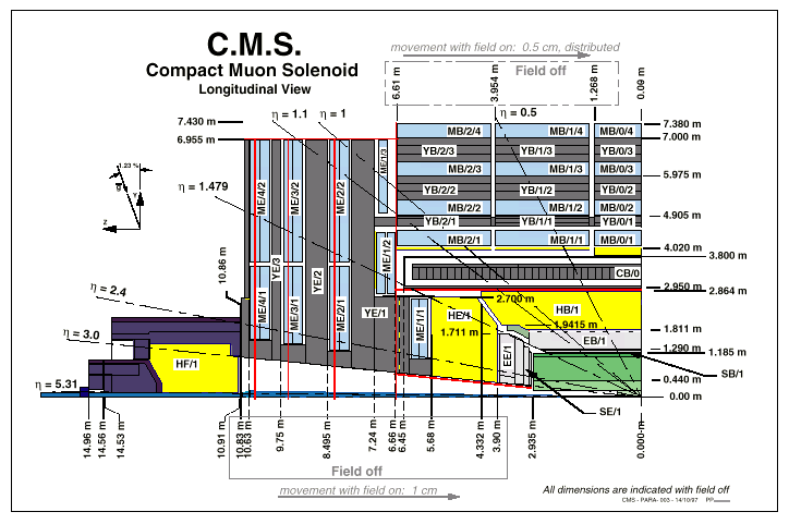
which includes marks and dimensions. A Longitudinal and transverse view of the detector can be seen here:
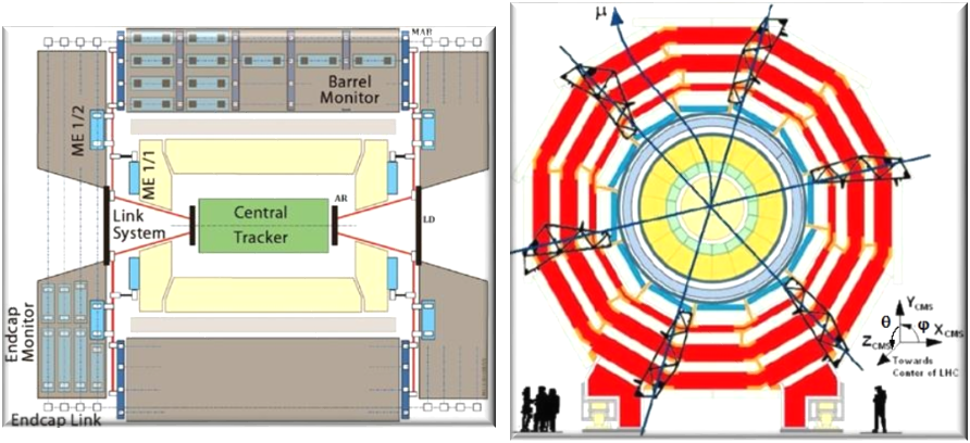
where the three alignment planes are shown. Finally, an overall layout of CMS is shown here:
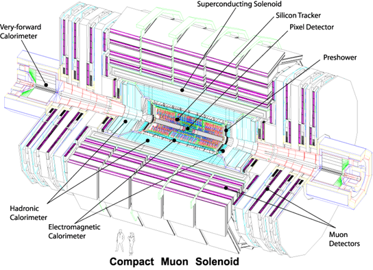
The muon system consists of about 25000 detection planes embedded in the 15 m diameter, 20 m long return yoke. To cope with all the muon momentum resolution requirements, the system is instrumented with a complex opto-mechanical Alignment System organised in three basic blocks:
- The Tracker internal alignment, to measure the positions of the various modules and monitor the eventual internal deformations.
- The Muon Systems (Barrel and Endcaps) internal alignment, to monitor the relative position among the chambers.
- The Link System, to relate the position of the various elements of the muon system (barrel and endcaps) with the position of the Tracker body, and to monitor the relative movements between both systems.
We show in the second figure one of the phi alignment planes where the three alignment subsystems can be seen. There are in total three phi planes. Each plane contains four independent alignment quarters where the three systems are connected.
The Tracker Alignment
The alignment of the tracker units (silicon sensors) is done with internal laser beams
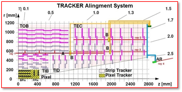
The Laser Alignment System (LAS) [10] uses infrared laser beams to monitor the position of selected tracker modules. It operates globally on tracker substructures and cannot determine the position of individual modules. The goal of the system is to generate alignment information on a continuous basis, providing the geometry of the tracker substructures at the level of 100 microns. In addition, possible tracker structures movements can be monitored at the level of 10 microns using offline alignment algorithms based on the information of the tracks crossing the detectors.
In each Tracker Endcap structure (TEC), 8 axial laser beams, distributed in R and Phi, cross all 9 endcap discs. At each TEC end-face, 3 mechanical supports –pillars- rigidly attached to the most external (9th) disc transfer the internal tracker geometry information to the outside world. The relation between the position of the Tracker body and the Muon Chambers systems (barrel and end-caps) is done through the Link System, and in particular by means of 12 laser beams (6 on each side) housed on a carbon fibre structure (Alignment Ring, AR) which is supported by the 3 TEC pillars. Its position and orientation is therefore known precisely in the tracker coordinate system. The goal is to monitor motions of the Muon structures with respect to the Tracker system with an accuracy of about 200 microns.
The Barrel Alignment
The Barrel Alignment system [3] measures the positions of the barrel muon chambers with respect to each other and to the whole barrel muon spectrometer.
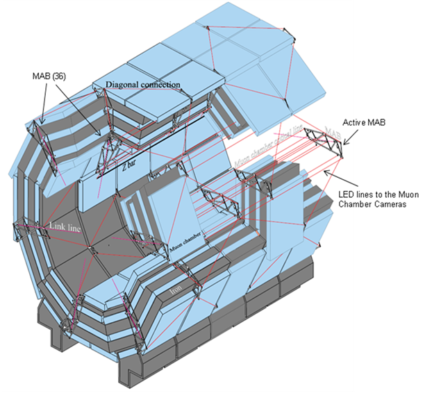
Each barrel muon chamber is equipped with light sources (LEDs, more than 9000 in total). The LEDs are observed by small video-cameras (600 in total) mounted on rigid carbon-fibre structures called MABs (Module for the Alignment of the Barrel). There are direct observations between the MABs called diagonal connections.
The system is completed with long carbon fibre bars called z-bars fixed to the vacuum-tank of the magnet. The z-bars (12 in total, 6 per side) are also equipped with LED light sources and observed by video-cameras mounted on the MABs. The MABs (36 altogether) are fixed to the return yoke in the gaps between the barrel wheels (6 per gap) and on both ends of the barrel (6 per side). The MABs on the two ends, containing Link and Endcap elements, are used to connect the three alignment subsystems to each other.
The Endcap Alignment
The Endcap Alignment system [11] is designed to monitor the relative positions of the CSC chambers. The system uses a complex arrangement of 5 types of sensors for the transferring and monitoring of the Phi, R, and Z coordinates. It measures only a set of selected chambers per layer, in total a sixth of all endcap chambers.
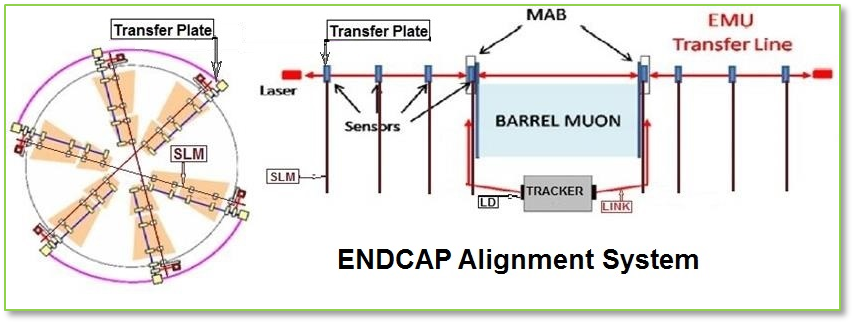
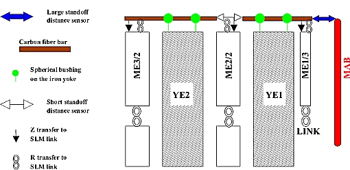
The main monitoring tools within the RPhi plane are the Straight Line Monitors (SLM). Each SLM consists of 2 cross-hair lasers, which emit a nearly radial laser beam across 4 chambers from each end, and provide straight reference lines that are picked up by 2 optical sensors (Digital CCD Optical Position Sensors, DCOPS) placed at each CSC chamber. The Phi coordinate alignment is handled by optical SLMs and transfer lines. Transfer lines run parallel to the CMS Z-axis along the outer cylinder envelope of CMS at 6 points separated 60º in Phi. Transfer lines allow connecting optically the full barrel and endcap muon structures.
The Link Alignment System
The purpose of the Link Alignment System is to measure the relative positions of the muon spectrometer and the tracker body in a common CMS coordinate system. It is designed to work in a challenging environment of very high radiation and magnetic fields; meet tight space constrains, and provides high precision measurements over long distances.
A distributed network of Amorphous Silicon Position Sensors (ASPDs) placed around the muon spectrometer and tracker volumes are connected by laser lines. An ASPD sensor [12,13] consists of two groups of 64 silicon micro-strips, with a pitch of 430 microns, oriented perpendicularly. The intrinsic sensor position resolution is better than 5 microns. The centring of the sensor in its mechanical mount was measured with 3D and 2D coordinate measuring machines with a precision in the range 5-10 microns.
The entire Link System is divided into three Phi planes 60o apart starting at Phi = 15o. Each plane consists of four independent quadrants, resulting in 12 laser paths, or lines: 6 on each side (positive or negative Z) of the CMS detector. Next figure shows a sketch of a quarter of Phi plane with its instrumentation. The three laser light paths, originated at three different regions, Tracker, EndCap, and Barrel, are shown in next figure. All laser sources-collimators are housed in carbon fibre structures called ARs (Alignment Rings), MABs, and LDs (Link Disks).
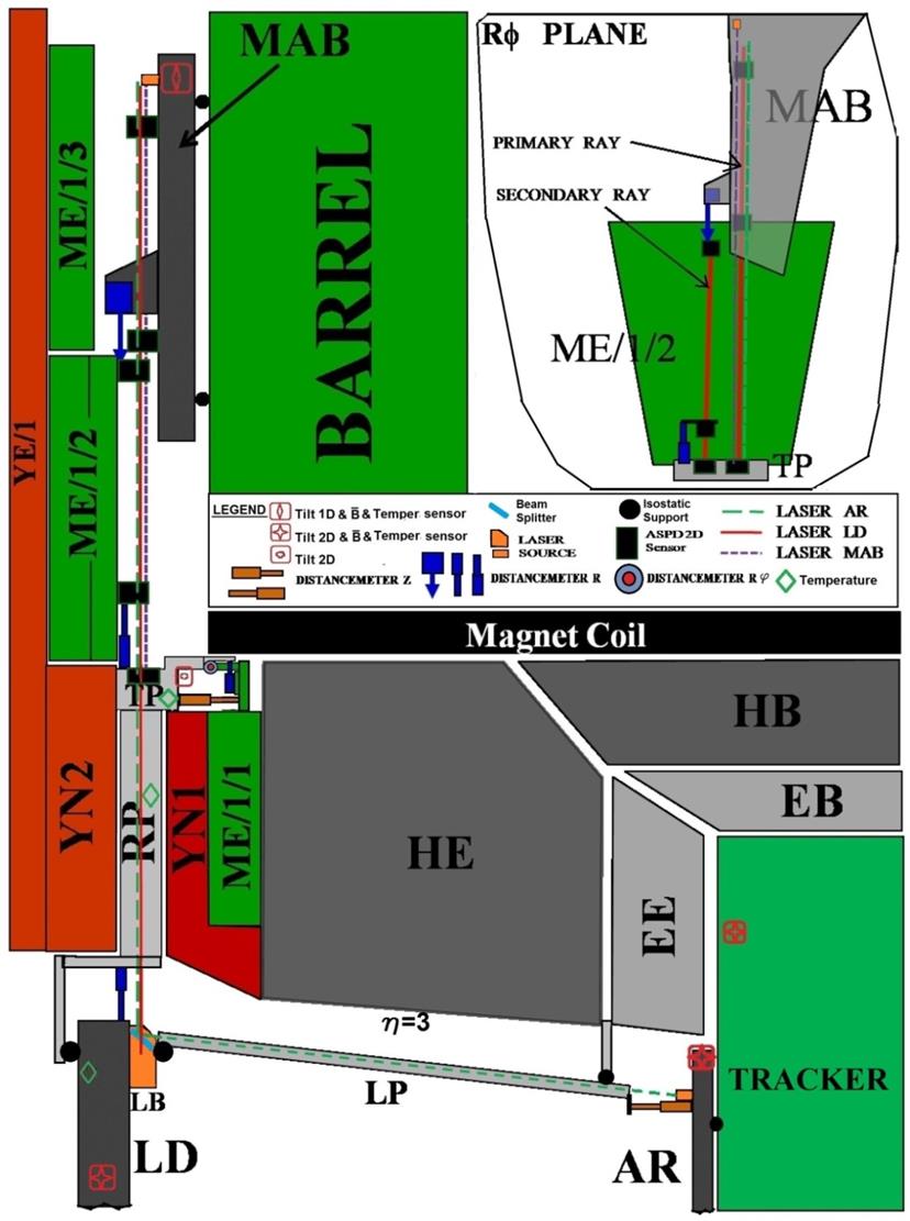
The AR’s, rigid carbon fibre annular structures, are placed at both ends of the tracker. The LD is suspended from the outer diameter of the YN/1 iron disk of the end-cap muon spectrometer by means of aluminium tubes attached to the mechanical assemblies called Transfer Plates (TP). MABs are mounted onto the barrel yoke
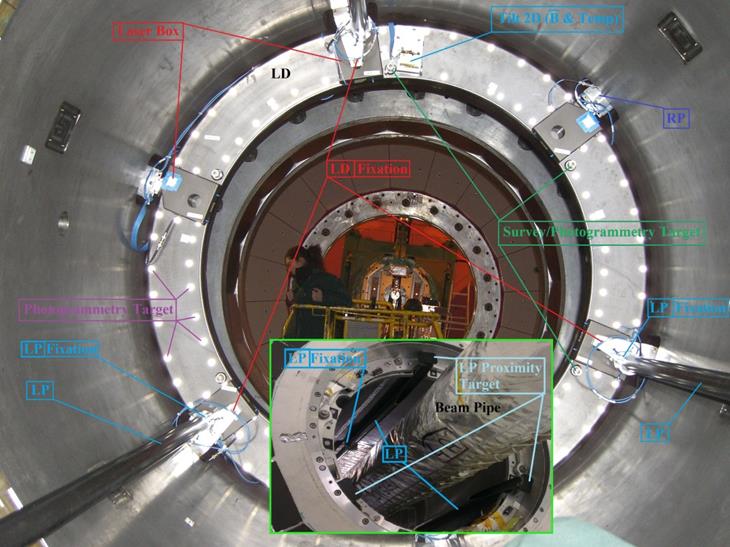
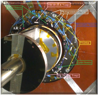
The ME/1/1 and ME/1/2 disks of chambers of the end-cap muon spectrometer are linked to the Tracker and the barrel muons via the laser paths and opto-mechanical sensors installed in the TPs and MABs.
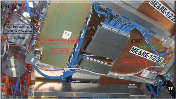
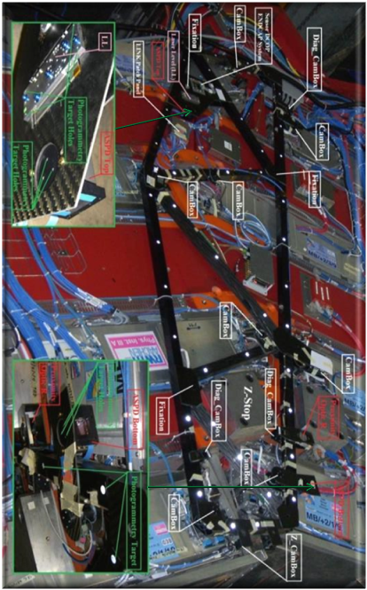
The multiple lasers-ASPDs link measurement network is complemented by electrolytic tilt-meters (for angular measurements with respect to the gravity vector of the elements to which they are attached), proximity sensors (optical and mechanical, for short distances measurements), aluminium tubes for long distances measurements, magnetic probes and temperature sensors.
The monitoring of the relative displacements (along Theta and RPhi directions) between some CMS elements, relevant for the system, is done with the help of aluminium bars (longitudinal and radial profiles, labelled LP and RP) for long distances, and contact and non contact proximity sensors for short distances. Changes in length of the aluminium profiles due to temperature variations are controlled by the readout of the appropriate temperature probes.
A 3600 mm long LP relates LD and AR approximately in the region eta=3. On its closest end to the AR a target is in contact with a potentiometer [14], located at the AR, allowing to monitor the relative distance between LD and AR structures along the CMS Z coordinate, at three different Phi positions. The other Z monitoring in a Phi quarter is the relative distance between the TP and the ME1/1 chamber. This is done also with a contact potentiometer installed in the TP, which rod touches a target situated on the top side of the ME1/1 chamber.
The rest of the relative distance measurements between CMS elements, in a Phi quarter, monitor eventual motions in the RPhi direction. The longest monitored distance is the one between LD and TPs. A 1977 mm long radial profile, instrumented with a potentiometer in the closest end to the LD, measures the LD to TP relative distance. Relative displacements between the TP and the bottom side of the ME1/2 chamber are monitored as well using contact potentiometers. The RPhi relative distance between the MAB structure and the top side of the ME/1/2 chamber in the corresponding Phi quarter, is monitored with a non-contact proximity device [15]. A sensor is installed at the bottom place of each MAB structure. The sensor emitting/receiving head directs a laser light and receives the reflected light to/from a target located on the top region of the ME/1/2 chamber. All proximity measurements along RPhi are labelled as Distancemeter R.
Concerning measurement errors, the length of the longitudinal profiles are determined with an error smaller than 30 microns. The lengths of the various sensor mechanical supports are measured with a 3D measuring machine with a precision in the range 5 - 10 microns. The typical precision in the short-distances measurement with the contact and optical sensors used in the Link System stays, according with our bench calibrations [16], in the region 30 − 40 microns. However, the uncertainty in the spatial location of sensors related to the mounting in CMS is never smaller than 300 microns.
The estimated combined errors (mechanical support length plus proximity sensor output plus the mounting uncertainty) in the measurements of absolute positions, is about 305 microns. Nevertheless, the relative distances measurements are only affected by the precision of the proximity sensors, ~ 40 microns.
Complementing the laser and distance measurement system, all the alignment structures (ARs, BDs, LDs, TPs, and MABs) are instrumented with different models of tiltmeter sensors [17 and 18] which provide direct information on changes in orientations, with a precision of ~ 40 microrad.
CIEMAT Contributions
CIEMAT in collaboration with the IFCA (Instituto de Física de Cantabria) have been done rigorous studies to select the different types of detectors and components used by the LINK:
A particularly great effort was dedicated to the photodetectors to be used. In fact, for several years groups at IFCA and CIEMAT, together with the Steinbeis-Transferzentrum für Angewandte Photovoltaik und Dünnschichttechnik (STW) were carrying a joint R&D effort to develop a new generation of semitransparent Amorphous silicon 2D Position Detecting sensors (ASPDs) for multipoint alignment purposes.
For the generation of the optical lines the LINK system have been selected the laser diodes 58FCM model of the firm Shäfter&Kirchhoff located on the outside of the experimental cavern to avoid the effects of magnetic field and irradiation. The guidance of the light until the collimators located in detector is carried out using single-mode optical fibres S630 of Nufern, that were selected after experimental study of their behaviour face to the radiation levels expected. The collimators chosen belong the model FC5-tifs-NIR from Micro Laser. Among the tested devices were the only ones capable of provide a gaussian beam without distortion or effects of diffraction in the distance ranges planned to use in CMS. It should be noticed that the paths of the laser beams have been protected and anodized in black to prevent, or minimise, reflections.
To monitor rotations three different types of electrolytic tilt sensors are used in the LINK Alignment System: the uniaxial M756-1172, the biaxial M756-1150, and the biaxial 900-H all of them from the firm Applied Geomechanics Inc. The sensors have been calibrated in the range the expected rotations of elements in CMS.
Concerning the measurement of distances between CMS mechanical elements two types of distancemeters have been used and calibrated: the non-contact (optical) OMRON Z4M-W100 of the firm 'OMRON Corporation' and the potentiometers 18FLPA50, from Sakae, and the SLS095-10 from Penny & Giles.
We have, in addition, studied the effects induced by the expected changes of temperature, the absorbed irradiation doses and the magnetic field on those elements.
The so-called opto-mechanical assemblies are formed by a combination of mechanical, optical and detecting devices, in the same element, named: Laser Box (LB), Detector Box (DB), Transfer Plate (TP), Laser Level (LL), Alignment Ring (AR) and LINK Disc (LD). All of them have been developed for us on the basis of the LINK system requirements and have been adjusted, calibrated and studied, using complex optical benches instrumented with 'ASPDs' sensors which have been specially designed for this purpose.
References
[1] CMS Collaboration, “The CMS experiment at the CERN LHC”, JINST 3 (2008) S08004.
[2] The CMS Collaboration, “The Magnet Project Technical Design Report”, CERN/LHCC 97-10.
[3] The CMS Collaboration, “The Muon Project Technical Design Report”, CERN/LHCC 97-32.
[4] The CMS Collaboration, “The Tracker Project Technical Design Report”, CERN/LHCC 98-06.
[5] V. Karimaki and G. Wrochna, CMS TN/94-199; F. Matorras and A. Meneguzzo, CMS TN/95-069 and I. Belotelov et al. CMS NOTE 2006/017.
[6] “The CMS Magnet Test and Cosmic Challenge (MTCC Phase I and II), Operational Experience and Lessons Learnt” CERN/LHCC 2007-011, LHCC-G-129, CMS Note 2007/005, March 7, 2007.
[7] L.A. García-Moral, E. Calvo, et all, ‘Motions of CMS detector structures due to the magnetic field forces as observed by the Link alignment system during the test of the 4 T magnet solenoid’, Nuclear Instruments and Methods in Physics Research A 606 (2009) 344–361.
[8] P. Arce, E. Calvo, et all, ‘CMS structural equilibrium at constant magnetic field as observed by the link alignment system’ Nuclear Instruments and Methods in Physics Research A 675 (2012) 84–96.
[9] P. Arce, E. Calvo, et all, ‘Motion of CMS detector and mechanical structures during Magnet Cycles and Stability Periods from 2008 to 2013 as observed by the Link Alignment System’, Nuclear Instruments and Methods in Physics Research A 813 (2016) 36–55.
[10] The CMS Collaboration, “The Tracker Project Technical Design Report”, CERN/LHCC 98-06.
[11] Marcus Hohlmann et al., “Design and Performance of the Alignment System for the CMS Muon Endcaps”. CMS CR-2008/016
[12] A. Calderón et al., Nucl. Instr. and Methods A 593 (2008) 608– 615.
[13]"Amorphous Silicon Position Detectors for the Link Alignment System of the CMS
Detector: Users Handbook", A. Calderón et al., Informes Técnicos Ciemat 1126, December 2007.
[14] Sakae Tsushin Kogyo Co., Ltd. - Trade Dept. 322 Ichinotsubo, Nakahara-ku, Kawasaki-city, Kanagawa-prefecture, 211-0016 Japan.
(htpp://www.sakae-tsushin.co.jp)
[15] Omron Corporation, Tokyo Head Office, 3-4-10 Toranomon Minato-ku, Tokyo 105, Japan. (http://www.omron.com).
[16] “Proximity sensors Link Alignment System of the CMS Experiment: Users Handbook”, J. Alberdi et al. Informes Técnicos Ciemat 1107, May 2007.
[17] Applied Geomechanics Incorporated. 1336 Brommer Street, Sanya Cruz, CA 95062 USA. (http://www.geomechanics.com/).
[18] J. Alverdi, E. Calvo, et all, ‘Electrolytic tiltmeters inside magnetic fields: Some observations’, Nuclear Instruments and Methods in Physics Research A 574 (2007) 199–201.
