The CMS Drift Tube Chambers
The Drift Tube (DT) chambers are a fundamental component of the CMS detector, further information of the DTs can be found here. Their aim is to identify, measure and trigger on muons from LHC collisions in the central part of the detector. Each chamber is a gaseous detector composed by hundreds of individual measurement units called "cells", capable of reconstructing muon tracks on a large detection surface. Many interesting physics signals from CMS contain high momentum muons, therefore a highly performant muon system is fundamental.
Our group has been a member of the DT group since the first stages of the experiment. We have participated in the design and assembly of the system, having built in our workshop almost 30% of the detector, and most of its readout electronics. Further information about the CIEMAT DT electronics can be found here. Since more than 15 years the construction, tests, commissioning, operation, maintenance and upgrade of the detector are one of the main activities of our group.
- DT description
- Operation
- DT Electronics
- HL-LHC and CMS upgrade
The basic element of the DT chamber is the drift tube, which has cross section dimensions of 13 mm x 42 mm. The total number of sensitive cells is around 172,000. Any charged particle going through the cell volume will generate a signal (hit) in its anodic wire that will be amplified and discriminated by the front-end electronics for further time digitization. The position of the charged particle can be related to the time measurement since the drift velocity in the cell volume is approximately constant. The maximum drift time in each tube is around 400 ns and the spatial resolution that can be achieved at the cell level is in the order of 250 µm.
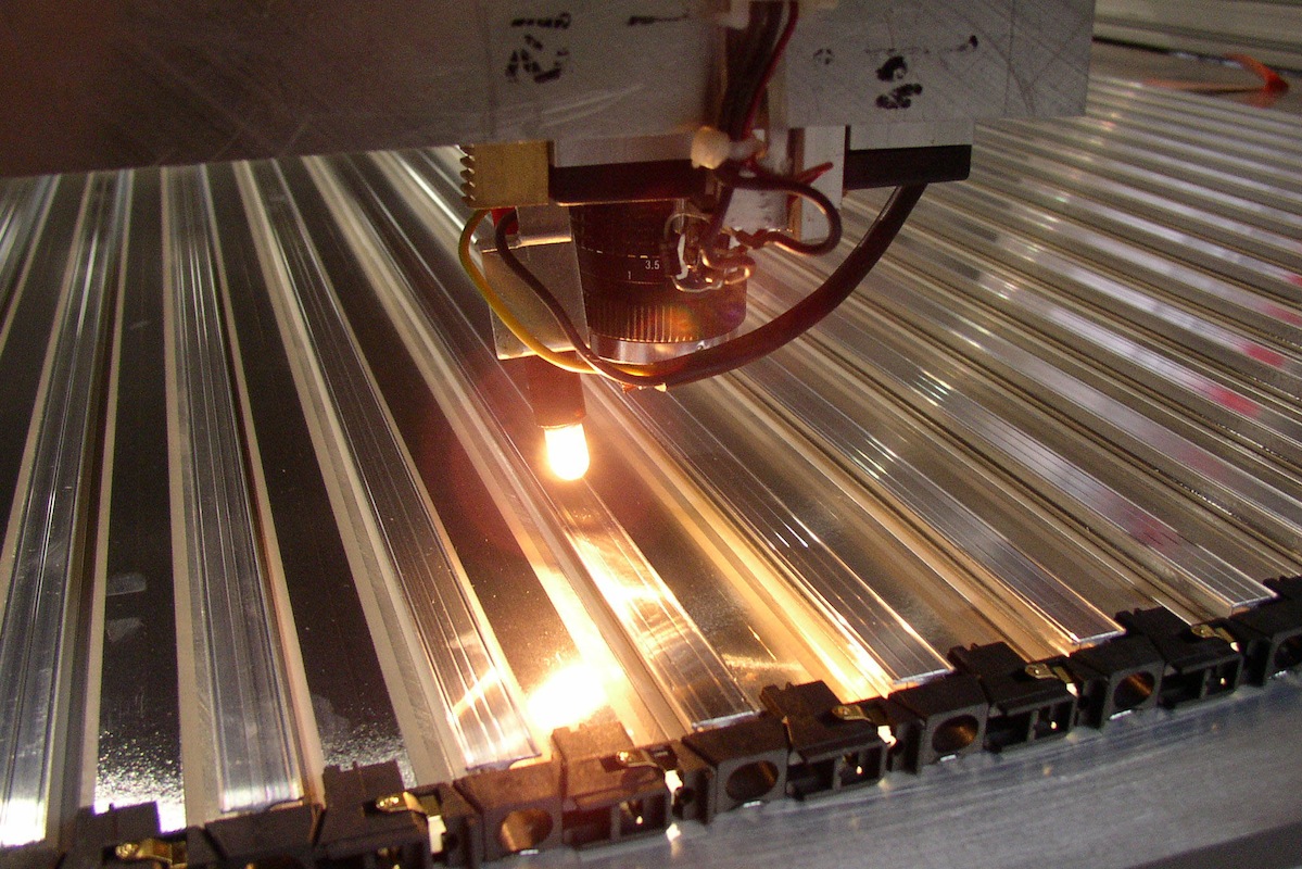
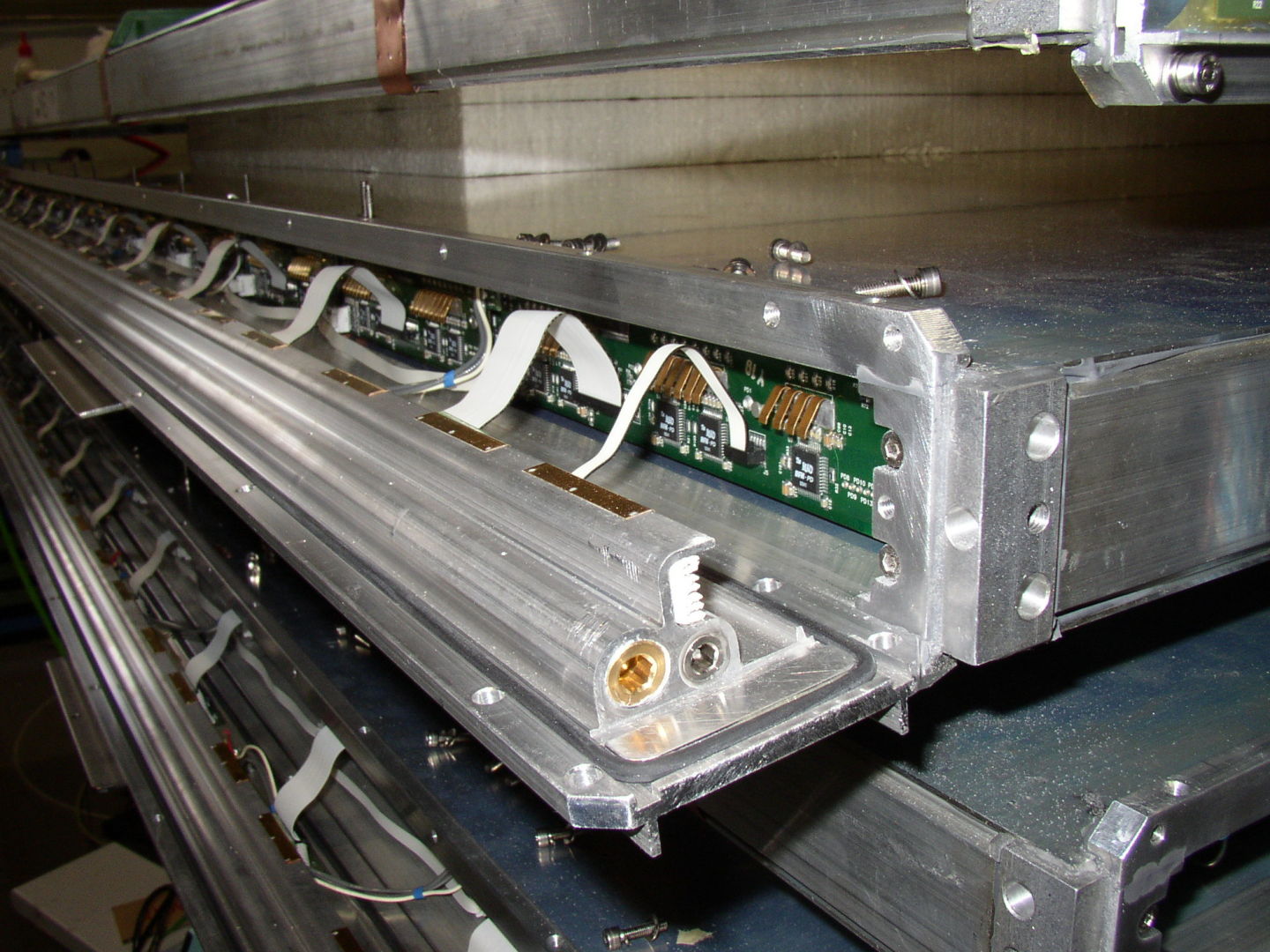
Images of a DT chamber during assembly.
A DT chamber is made of three (or two in MB4) Superlayers (SL), each consisting of four layers of rectangular drift cells staggered by half a tube width. The wires in the two inner and outer SLs are parallel to the beam line and provide the track measurement in the magnetic bending plane (r, Ф). In the central SL, the wires are orthogonal to the beam line and measure the position along the beam. This inner q Superlayer is not present in the MB4 chambers, which therefore measure only the Ф coordinate.
The DT chambers are installed in the five wheels of the return yoke of the CMS magnet (named YB-2, YB-1, YB0, YB+1 and YB+2). Each wheel is divided in 12 sectors each covering ~30º around the interaction point and each sector is organized in four stations of DT chambers named MB1, MB2, MB3 and MB4 going from inside to outside, where MB stands for Muon Barrel. There are a total of 250 DT chambers in CMS.
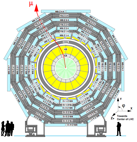
Transverse view of the CMS detector.
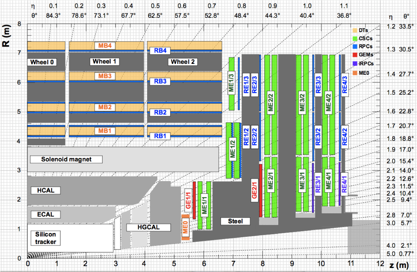
Image of a quadrant of the CMS detector with the view of all the muon systems.
CIEMAT group has participated intensively in the commissioning of the CMS detector and continues participating in its operation, from central shifts to expert interventions as well as detector performance studies.
This activities are focused mostly in the DT detector and expand from the operation during LHC physics production to the shutdowns where interventions in the detector take place.
Image of one of our collegues in the CMS control room at P5 (Cessy).
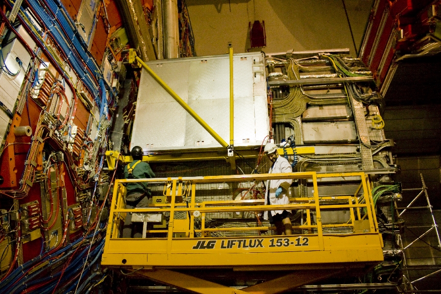
Image of interventions in a DT chamber at the CMS detector.
The Drift Tube electronics receives the signals from the anode wires through the Front End Boards (FEB) which are located inside the chamber gas volume. The FEB amplifies, shapes and discriminates the chamber signals and forwards them to the two electronic chains, the DT readout and the DT trigger.
DT read-out electronics is designed to perform time measurement of the chamber signals that will allow the reconstruction of charged particle tracks and precise momentum measurement. A large fraction of this electronics has been designed and built at CIEMAT and information can be found at the DT ELECTRONICS site. There are several levels of data merging in order to achieve a read-out of the full detector at a Level-1 trigger rate of 100 kHz.
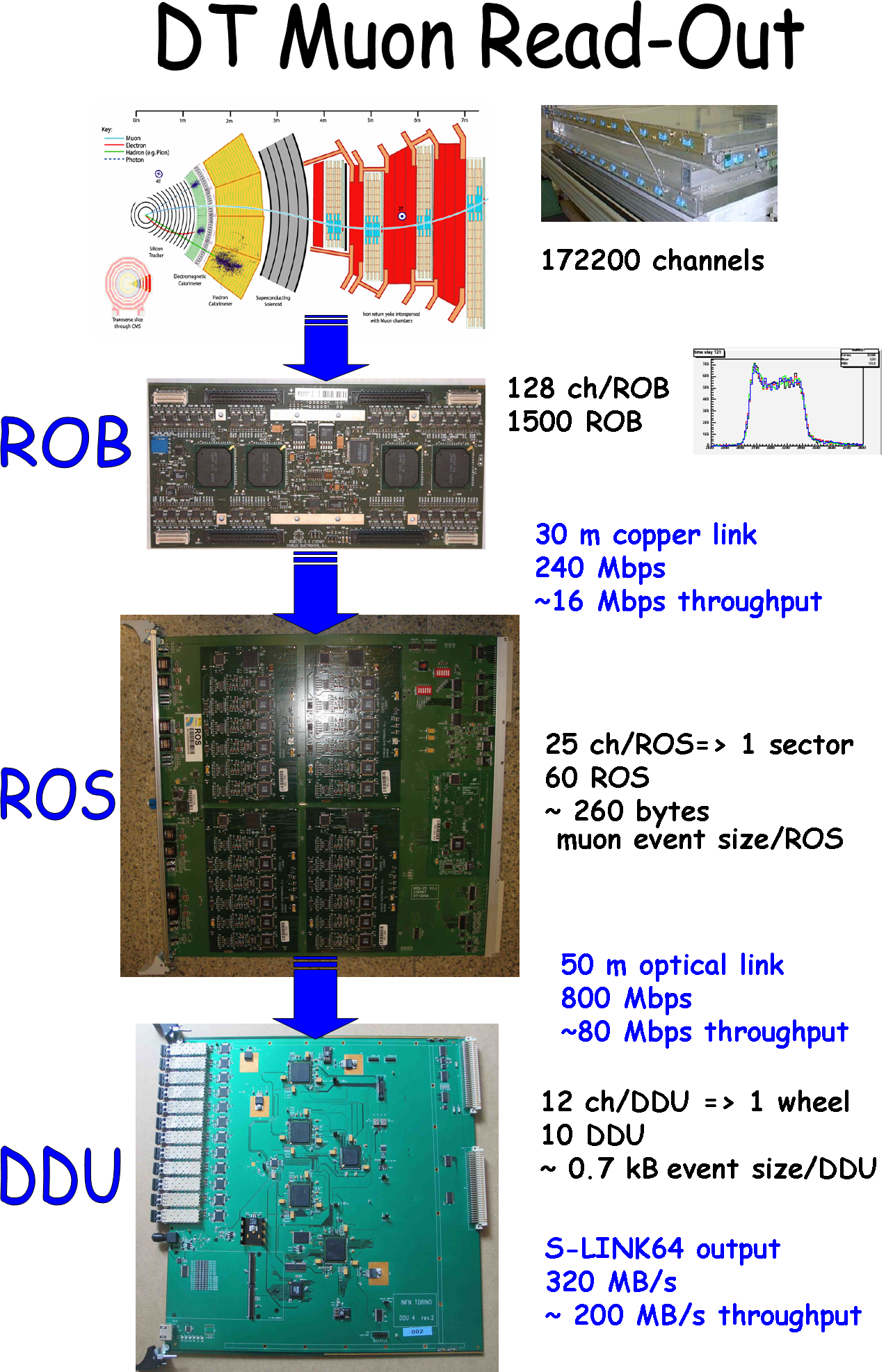
Schematich view of the DT detector readout chain.
First elements are the ROBs (Read Out Boards), based on the ASIC HPTDC (High Performance Time to Digital Converter), that perform the time digitization of the hits and assign them to the Level 1 trigger. They transmit their data through a ~30 meter copper link to the 60 ROS (Read Out Server) boards located in the tower racks in the cavern. ROS boards are in charge of merging the information from one sector and perform several tasks of data reduction and data quality monitoring. Each sector event is retransmitted through an optical link to the DDU (Device Dependent Unit) boards located in the counting room. The DDU boards merge data from up to 12 ROS to build an event fragment and send it to the global CMS data acquisition system through an output at 320 MBps.
One of the key features of the DT system is its robust and reliable trigger system, with precise bunch crossing assignment. (BX stands for bunch crossing, and refers to each 25 ns unit time in which collisions may occur in CMS.) This trigger system is based on the Mean-timer algorithm and allows reconstructing tracks from the drift time measurements. For each BX the DT local trigger system provides up to two trigger segments per chamber in the Ф view, and one in the q view. In the Ф view, each trigger segment is associated with the following quantities: the BX, at which the corresponding muon candidate was produced; the position and direction in the local coordinate system of the chamber; a quality word describing how many aligned DT hits were found; and a bit flagging the segment as a first or second candidate, ordered according to their assigned quality. One set of such quantities is called a “trigger primitive”.
The trigger algorithm that provides the trigger primitives in the Ф view works in three logical steps that are sketched below. The Bunch and Track Identifiers (BTIs) search for track segment candidates made of three or four aligned DT hits within a SL in every BX. Each candidate is processed by the Track Correlators (TRACOs), which search for a proper angular matching between the candidates from the two SLs in each chamber. TRACO candidates are then sent to the Trigger Server, which performs a ghost-suppression mechanism and then selects the two trigger primitives with the highest quality.
These two trigger primitives are sent to the Sector collector boards located in the CMS tower racks. They perform trigger synchronization and send the encoded information of position, transverse momentum and track quality through high-speed optical links to the DT Regional Trigger in the counting room. The Regional Trigger builds full muon tracks and forwards the best four muon candidates to the CMS Global Muon Trigger where information is combined with that of the other muon detectors.
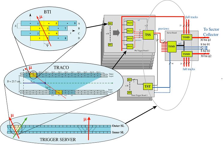
The main components of the DT local trigger in the Ф view of a muon chamber. The BTIs detect hit alignments within each Superlayer, the TRACOs search for proper matching between SLs and the Trigger Server selects the best two candidates in the chamber and applies a ghost-suppression algorithm.
The electronics described here is the original design from CMS with which we have been taking data during LHC physics production program called Run 1 (from 2009 to 2013). Successive upgrades in the following years are modifying this system and this are described in the DT upgrade pages.
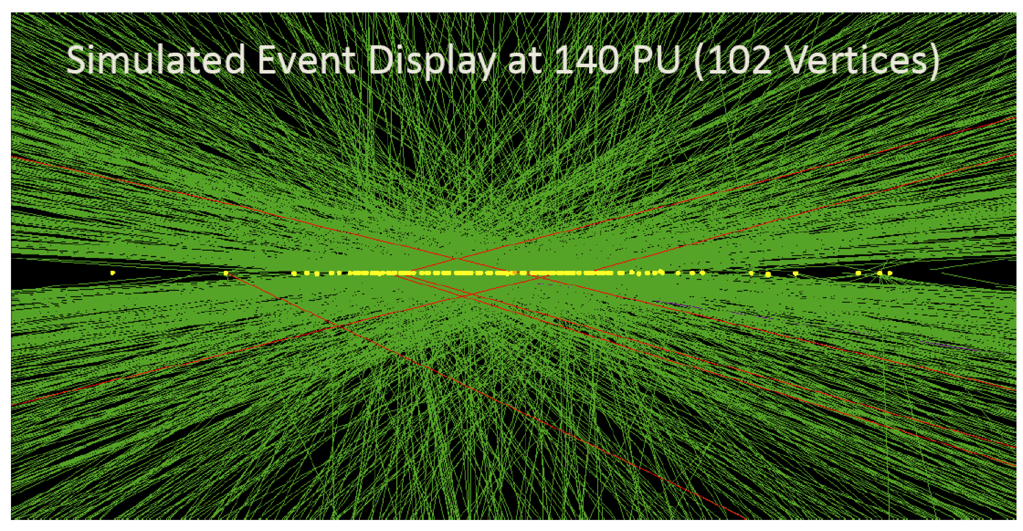
The LHC was originally designed to achieve 14 TeV in the center of mass and 1034 cm-2 s-1 instantaneous luminosity. During Run 1 LHC operated at a reduced energy of 7 TeV and 14 TeV was only achieved during Run 2, after the Long shutdown of 2013-2014. The LHC accelerator program forsees during its lifetime a series of upgrades that will allow to improve its performance to maximize physics production. There are two main upgrades foreseen, one of them that will drive the instantaneous luminosity up to a factor 2 the nominal design and another one that aims at obtaining up to a factor 10 the integrated luminosity, so called HL-LHC (High Luminosity LHC).
The HL-LHC has been identified as one of Europe’s highest priorities for the next decade in the European Strategy for Particle Physics (CERN Courier July/August 2013 p9) adopted by CERN Council in the special session held in Brussels on 30 May 2013. The HL-LHC was also recently selected as one of the 29 landmark projects of the European Strategy Forum on Research Infrastructures (ESFRI) 2016 Roadmap.
The CMS detector has planned a series of interventions to accomodate to this LHC program that will pose significant challenges for radiation tolerance, occupancy and event pileup on the detectors. A first upgrade phase is called CMS Phase 1 Upgrade includes all the activities to operate with a luminosity of up to 2 1034 cm-2 s-1. It is followed by a CMS Phase 2 Upgrade that includes all the activities to get the detector ready for HL-LHC which is aimed at start in the Long Shutdown 3 in 2023-2025.
The DT detector has gone and is going through a series of upgrades to accomodate this program and they are described at the CMS Upgrade web page.
