Technologies used in the project
One important objective of the project is to implement technologies and methodologies that are useful to society.
We show in this section the technologies and methodologies used, grouped according their purpose.
Communication and dissemination technologies
During the project traditional media such as articles, brochures, information boards, posters, manuals, etc. will be used. There will also be communication in digital media through social networks (twitter, Facebook) which are cheap and effective methods to reach an audience.
To communicate the results of the project, seminars will be organized and there will be participations in conferences and technical seminars. One of the activities to be undertaken in one of the conference will be to organize a matchmaking. A matchmaking consists of quick meetings organised before or spontaneously after a small presentation of the participating companies. The goal is to take advantage of the public attending to a workshop to know several companies and have several meetings on the same day.
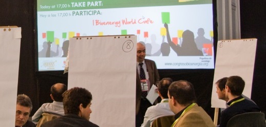
Finally, a World Café will be organized during Expobiomasa 2017. The World Café methodology was developed accidentally by American consultants Juanita Brown and David Isaacs in January 1995. It permits to discuss in depth specific issues, in order to reach new discoveries and opportunities for innovation, while consensus among participants achieved, facilitating the implementation of the decisions taken. It is based on the principle that small group there is more privacy and problems faced bluntly. The World Café method is a simple process. However, for each participant provides a maximum benefit. The basis of its philosophy is that each individual has the potential to create a great idea and sharing with others in a pleasant atmosphere, is the most powerful way to learn. One of the main aspects of the World Café is rotation around the tables. This generates constructive exchanges of ideas, which expands the knowledge of the participants and enriches the final result.
For its organization an atmosphere like in a Café is recreated and tables are prepared for 4 people. Cards, bookmarks and everything that encourages free discussion and documentation of the issues discussed are provided. 3 rounds of 30 minutes conversation are held at the end of which the conclusions are written on cards or sheets. For more information visit www.theworldcafe.com or other sites that explain how to organize it.
Combusion equipment
BOILERS:
In combustion tests carried out in B2, two boilers located at CEDER-CIEMAT have been used. Their thermal powers are: 40 kW and 500 kW:
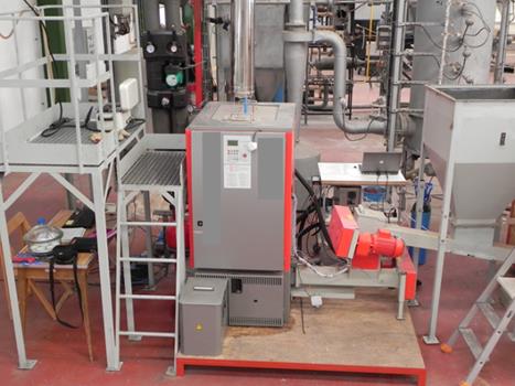
40 kWth boiler is a commercial boiler which has been specially designed for agro-fuels. It has a lateral feeding burner based on a moving grate with a double movement forward-backward and upward-downward. The feeding system is adapted to feed pellets, chips and chopped biomass. Furthermore, the boiler has a fully automatic ash extraction system. Regarding the heat exchanger, it is formed by vertical tubes with three smoke passes. Fumes are forced to flow by a fan which also introduces the primary and the secondary airs. On the other hand, the boiler has a lambda probe located at the flue gases stream which allows the control of the oxygen concentration in the outlet gases. The boiler is automatically controlled and it has been classified by its manufacturer as class 3 according to the UNE-EN 303-5:2013 standard.
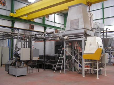
500 kWth boiler is a commercial moving grate boiler, in which primary air is introduced through several holes of the grate, while secondary air enters into the furnace through six nozzles, three in each side of the boiler. The boiler has a heat exchanger consisting of horizontal tubes with three smoke passes. Combustion air is introduced into the furnace by three fans (one for primary air and two for secondary air, one in each side of the boiler) and fumes are forced to flow by another fan. In order to remove particles from exhaust gases, a cyclone is used.
In the following figures, 40 kWth and 500 kWth boiler located at CEDER-CIEMAT can be seen:
EQUIPMENT FOR EMISSIONS MEASUREMENT
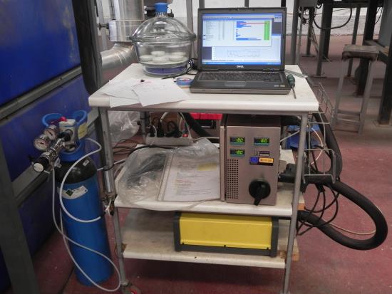
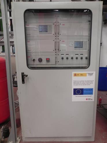
Measurement of the gaseous composition of exhaust gases during the combustion tests is carried out with a FTIR (Fourier transform infrared spectroscopy) analyser which has also a zirconium oxide cell for determination of O2 concentration in sample gas. Furthermore, during the combustion tests carried out in B2, a FID (Flame ionization detector) is used to determine the total organic compounds.
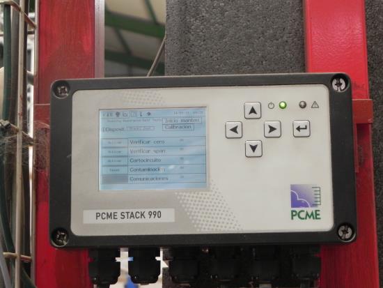
In B2, a continuous monitoring of the particles content in exhaust gases is carried out with a system which uses electrodynamic probe electrification technology. The electrical current produced by particles interacting with a grounded rod protruding across the stack is measured and correlated to dust concentration by comparison to the results of an iso-kinetic sample. Thus, an automatic iso-kinetic sampler is used to measure the particle content in flue gases in certain periods of time.
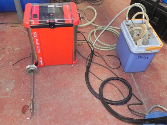
In B3, particles content in exhaust gases is determined with an automatic sampler using a pseudo-iso-kinetic sampling.
In the following figures can be seen respectively: FTIR analyser, Gases analyser with FID, equipment for the continuous monitoring of the particles and Automatic sampler for iso-kinetic or pseudo-iso-kinetic particle sampling.
Pre-treatment installations
PILOT PLANT FOR COARSE SIZE REDUCTION AND CLEANING
It has equipment for size reduction of biomass up to 10 mm. The main elements are a slow rotating double shaft shredder, a knife mill and rotary chopper for herbaceous material. The shredder has a power of 22 kW, the knife mill has 30 kW and the rotary chopper, 15 kW. Installation allows us to reduce the size of any material: branches, bales, stumps, pallets and biomass residues of various kinds. The equipment contains also a line for air and screening separation of mineral and light materials (leaves, needles, bark stones, sand, dust etc) and metal by magnetic separation, prior to the mills. Capacities are in the range between 200 and 1000 kg/h depending on initial and final characteristics.
Consta de equipamiento para la reducción de tamaño de biomasa hasta 10 mm. Los equipos que forman esta instalación son un triturador de giro lento, un molino de cuchillas y una rotopicadora para pacas de material herbáceo. El triturador tiene una potencia en motor de 22 kW y el molino de cuchillas de 30 kW. La rotopicadora tiene un accionamiento de 15 kW. La instalación permite reducir el tamaño de cualquier material: ramas, pacas, tocones, palets y residuos de biomasa de diversa índole. Además se dispone de una línea de separación de impurezas minerales pesados y ligeros (piedras, arena, acículas, fibras de corteza, polvo etc.) y metálicas mediante separación magnética, previa a los molinos.

In 2014-15 a new installation with higher capacities has been implemented. The plant allows grinding from very big sizes such as stumps, big bales, logs, etc, up to fine particles (less than 4 mm) with capacities between 1000 and 2000 kg/h. The plant comprises a big pre shredder 90 kW(slow rotating single-shaft type), a postgrinder 75 kW(swinging hammer type) and a oscillating two deck screener. The plant allows to study and optimize the process aiming at lowering the energy demand of size reduction in a reliable full scale pre-treatment installation.


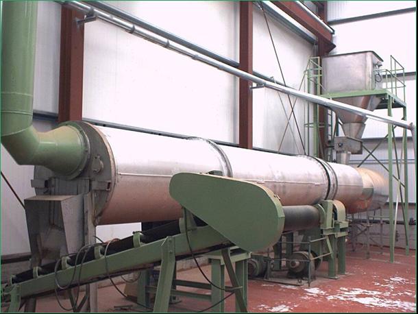
PILOT PLAN FOR ROTARY DRYING
PILOT PLAN FOR HYBRID SOLAR DRYING
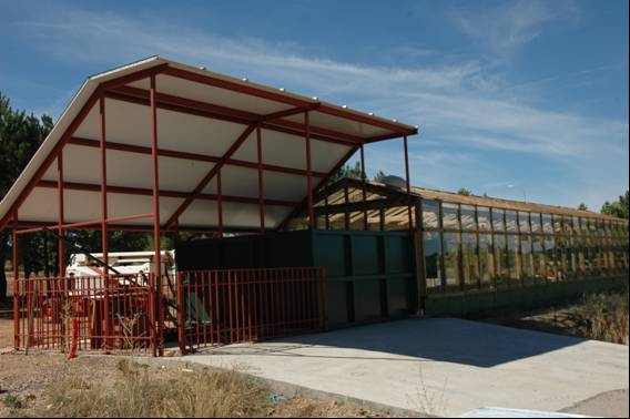
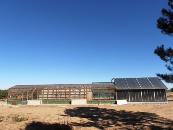
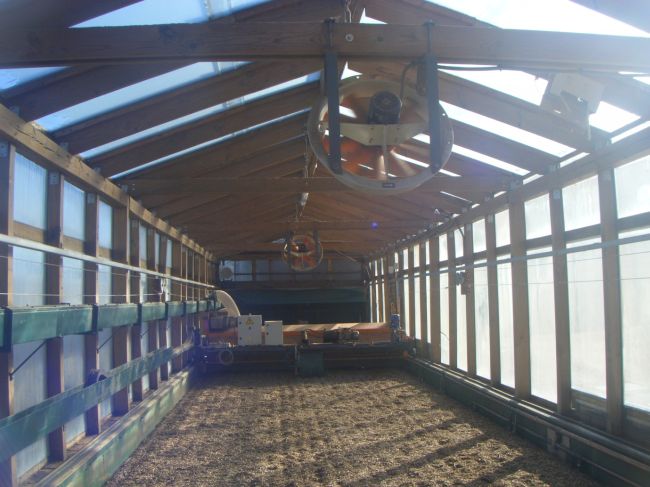
The dryer is a hybrid concept based on the heating of the biomass using solar radiation within a greenhouse enclosure and other indirect sources of low-temperature heat such as hot water from boilers, engine cooling systems or from heat exchangers of combustion gases.
The dryer is specially designed for automatically drying chipped or ground lignocellulosic biomass to values of 10-15% wet basis, which are usually required by pelletization industry. The innovation of this dryer lies in the integration of different heat supply systems with a design that enables a daily and seasonal constant output and stable in terms of moisture, maximizing the contribution of solar energy versus fuel utilization which contributes to the money and energy savings. The size of the drying tunnel is of 3,700 x 19,000 mm and has different elements to move the biomass and to transfer solar heat and other heat coming from a biomass boiler. The capacity reaches 200 kg/h of dry biomass (12% final moisture content) with a initial moisture content of 35%.
PILOT PLAN FOR PELLETIZATION
Biomass power plant
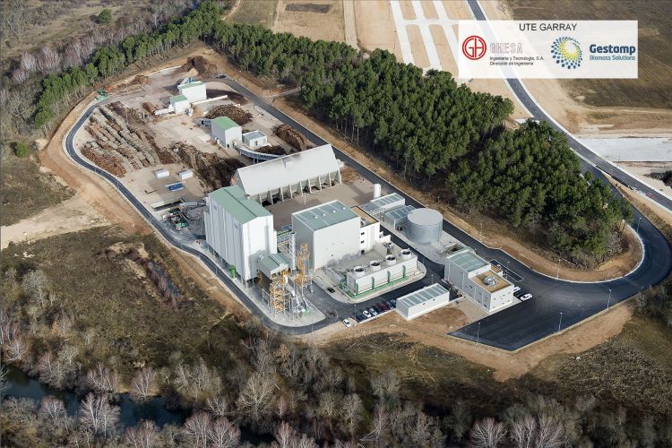
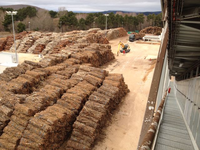
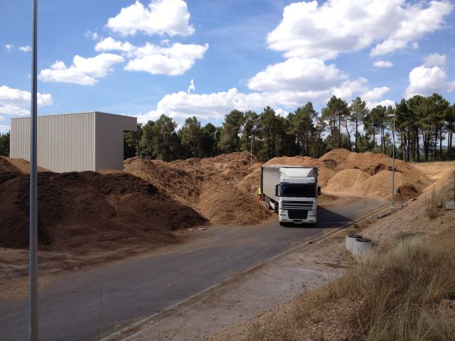
The power plant is designed to accept and process roundwood logs, brash bales and woodchips. Each fuel has its corresponding treatment through the different equipment that comprises the fuel handling system.
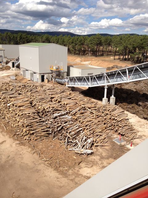
- Overband where metals are removed.
- Air classifier where stones are removed.
- Disc screen where oversizes are removed.
- Truck weight scale
- Conveyors (belt and chain conveyors)
- Belt weight scale
- Dust control systems
Thermal energy contained in the steam is turned into mechanical energy through steam expansion in the 15 MWe steam turbine giving rise to a revolving movement of the turbine rotor.
Mechanical energy is turned into electrical energy through the alternator which is connected to the turbine through a gearbox, which adapts rotor velocity to grid frequency.
Steam leaves the turbine in vacuum conditions (0.08 bar(a) and 41.6ºC) thanks to a water cooled condenser. The condenser is cooled by cooling water coming from the cooling towers. The cooling towers transfer the heat contained in the cooling water to the air that circulates within the towers.
The cycle is closed by means of pumping the water from the condenser to the deaereator with the feedwater pumps. Condensate water, low pressure steam coming from the turbine’s bleed and make-up water are mixed in the deaereator. The mixture is heated up to 120ºC and the gas dissolved components are removed.
There are two bleeds in the steam turbine in order to supply steam for preheating water before coming into the boiler (12 bar) and heating the mixture in the deaereator (2.5 bar).
Flue gases coming from the biomass combustion in the furnace cross the boiler transferring the energy to the water / steam in different stages: water walls, superheater, economizer and air preheaters.
After crossing the boiler, flue gases are treated in a system composed by multicyclone and fabric filter to reach a particle matter emission level below the environmental regulation.
Biomass will be dried and homogenized before coming into the boiler with exhaust gases from a 1,904 kWe natural gas engine. According to actual regulation, this engine can consume up to 10% of total primary energy. High and low temperature cooling water circuits will be also used to preheat condensate water and make-up water in the deaereator.
The control of all the parameters and processes in the power plant is carried out by a DCS.
Main parameters of the biomass power plant are:
- Biomass consumption (a.f. 36%): 115,500 t/year
- Operating hours: 6.500 h/year
- Primary energy consumption: 49,995 MWth LHV
- Net power capacity: 15,968 kWe
- Gross efficiency: 30.00%
- Net efficiency: 26.99%
Analysis methodology
1) Selection of sampling points prior to shrub clearance:
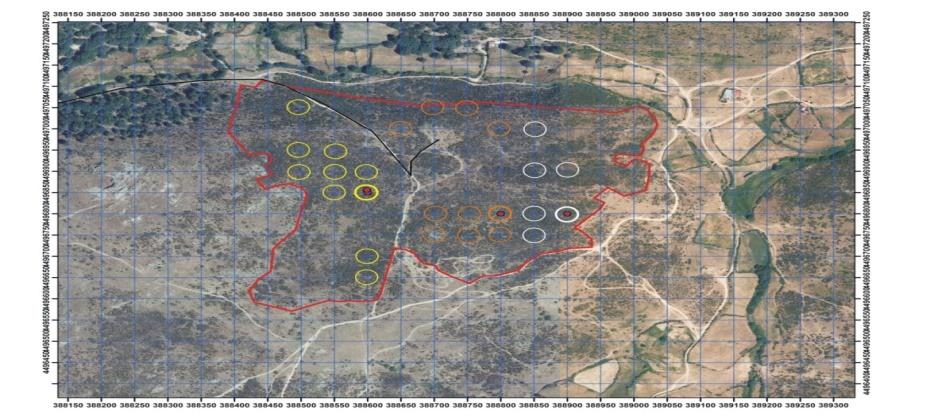
We overlayed a 50 x 50 m grid on each studied area using a geographic information system. On this grid, suitable sampling points were determined for the environmental impact assessment. An essential aspect taken into account in this selection was that the selected points presented the typical coverage of each area, avoiding edge effects and with no notable anomaly. Each area was then divided into 3 or 4 sub-zones (depending on the number of expected points) and a sampling point was established randomly in each sub-zone for subsequent positioning in the field.
2) Taking reference points:
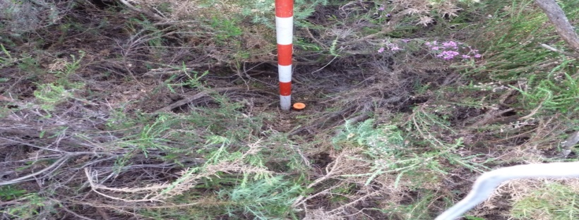
Once in the field, using a GPS, stands were redesigned as permanent plots (using real coordinates), and a stake was placed to facilitate future identification. Based on the reference point, a base line with a known direction (dependent on the plot) was established, along which vegetation transects and soil sampling were to be subsequently performed.
3) Vegetation transects and soil sampling:
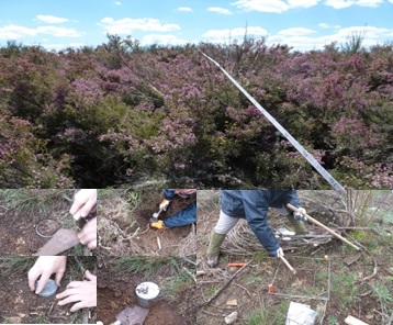
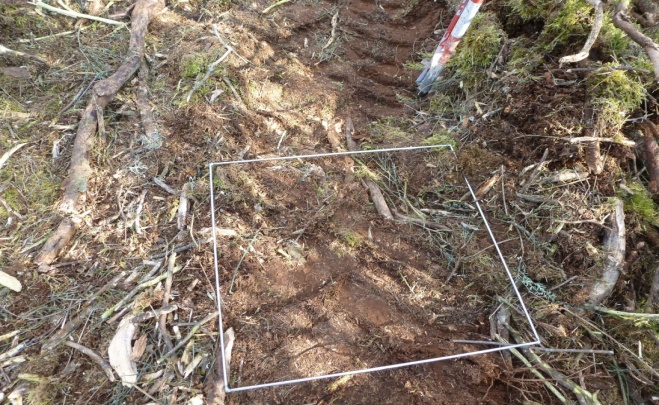
Perpendicular transects of 25 m in length were established. In each transect, the beginning and end were determined, the plant species as well as the height of each plant were recorded. We also identified whether the plant was alive or not and recorded the presence of bare soil, rocks, etc. As regards non-woody plants, we differentiated between annual and perennial grasses, other herbaceous plants and recorded the presence of non-vascular plants (ferns). Additionally, in the soil stratum, two squares (one 50x50 cm and the other 25x25 cm) were established to carry out the litter sampling. In this respect, we differentiated between the litter layer and recognizable remains (L), and fragmented and humified remains (FH), noting the depth of each of the strata. The material collected was then placed in separate plastic bags for subsequent transfer to the laboratory. In each of the stands, once the litter had been collected, a metal cylinder of 5 cm in diameter was insert
4) Calculation of biodiversity indices:
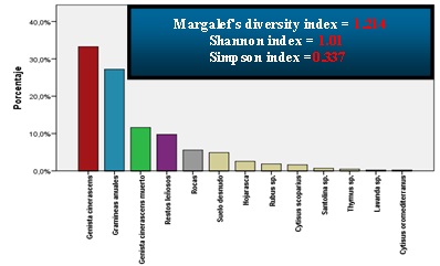
For each site, different indices such as richness (Margalef index), diversity (Shannon index) and dominance (Simpson index) were calculated, such that the comparison of the respective values obtained over the following two year monitoring period, would enable us to determine whether the clearance treatments lead to an increase in biodiversity at each of the studied sites.
5) Erosion risk evaluation in the vegetation transects:
During the first year (2015), we estimated several parameters (% of bare soil, existence of rocks, shrub cover, etc.) in each stand which, when evaluated alongside data from subsequent years (2016 and 2017), will allow us to identify and quantify the erosion risks associated with mechanized activities carried out as part of the project. As regards quantifying the erosive processes in the vegetation transects, a visual assessment was conducted in each of the stands and different codes were assigned to each erosive process identified.
6) Photointerpretation of shrub formations:
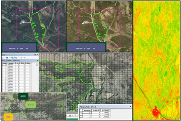
The natural evolution of shrub vegetation over time was interpreted from PNOA (Plan Nacional de Ortofotografía Aérea de España) orthophotos. For this purpose, we considered three categories: low open shrubland, open-shrub and closed-shrub. Thus, historical orthophotos from the year 2004 and current ortophotos from 2014 were entered in a geographic information system and an automatic digitizing raster by grids was used to compare and identify changes in shrubs categories over time. This task was performed for all the studied sites except Torretartajo (Soria), where the analysis was not possible due to the low quality of the orthophotos.
7) Dendrochronological analysis of shrub species:
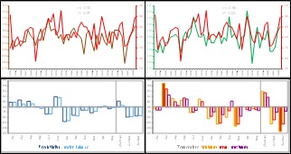
We estimated the average ages of the shrub species by counting tree rings. In addition, chronologies were obtained for each of the main species and were dated accurately. Furthermore, we established climate-growth relationships using climatic data from nearby climate stations. LINTAB was used as a tool for measuring tree rings and different statistical programs were used to crossdate the samples.
8) Assessment of forest fires risk:
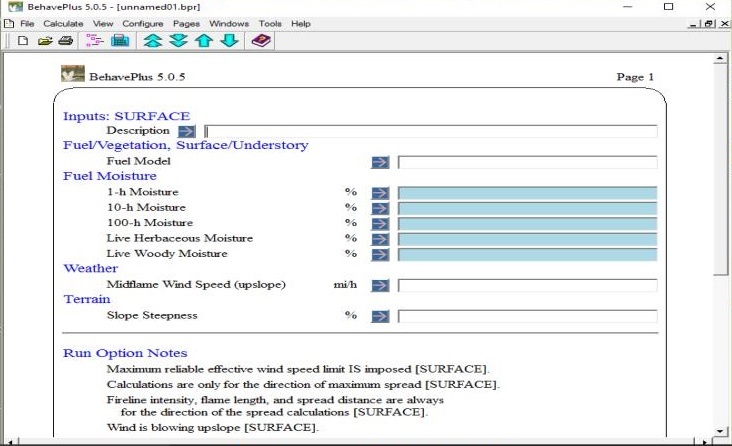
Our aim was to characterize and quantify changes in the combustibility of shrub formations subjected to mechanical clearing. For this purpose, data were gathered in the field (in control areas) which allow us to construct representative fuel models for the four studied areas. The data collected in field were used to develop site-specific models and simulations of forest fire behavior were created using specifically designed software.
9) Estimation of available shrub biomass:
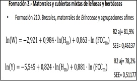
The available biomass of the main shrub species was estimated in each of the vegetation transects. This was done using biomass equations for shrub formations (Pasalodos et al. 2015), in which we entered the variables "height" and "canopy cover, fcc" obtained accurately during the establishment of the transects. In addition, certain restrictions such as legal considerations (protected areas), physiographic (slope) and environmental aspects (erosion and hydraulic public domain) were incorporated using a GIS to estimate the real biomass availability along a geographical gradient.
System of distributed heating at Las Navas del Marqués
INSTALACIONES DE BIOMASA DE LAS NAVAS DEL MARQUÉS
Las instalaciones de la red de calefacción distribuida (district heating) de Las Navas del Marqués, cuentan con una red de tuberías de 760 m (ida y retorno), para el abastecimiento de calor y ACS en los edificios públicos del Consistorio Municipal, un Centro de Usos Múltiples (edificio que alberga la unidad veterinaria, asociaciones vecinales, etc.), una sala de exposiciones, y la piscina climatizada municipal.
Para ello cuenta con una caldera de la casa DANSTOKER, modelo LH1000, con una potencia térmica de 1Mw (860.000 Kcal/h), pirotubular de parrilla fija, preparada para la combustión de virutas, serrín y derivados de madera, hasta un 25% de humedad.
En la siguiente imagen, puede verse la sala de calderas:
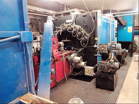
Posee las siguientes características:
- Quemador automático Mod. HBA-1000 especial para triturados de madera.
- Depurador de humos con sistema multiciclónico.
- Ventilador de tiro con transmisor de depresión y variador de frecuencia.
- Sistema de evacuación de humos homologado.
- Sistema neumático de limpieza automática de pirotubos.
- Sistema de control de combustión mediante sonda lambda.
- Sistema automatizado de extracción de cenizas y limpieza de horno.
La caldera se complementa con un sistema de alimentación mediante sinfines desde el silo, integrado en la sala de calderas, de piso móvil con descargador hidráulico. Todo el sistema está automatizado mediante panel de control eléctrico con sistema de regulación modulante y sistema Scada.
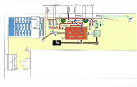
En la siguiente imagen, puede verse un esquema en planta de la sala de calderas:
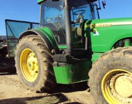
Equipment employed for biomass harvesting demonstrative trials
- Minimum power required: 200 horsepower
- Rolling system: 2 forestry tires (or reinforced)
- Other features: Rear linkage
- Front grille with protection
- Protection of rear window
- Protective cover under the tractor
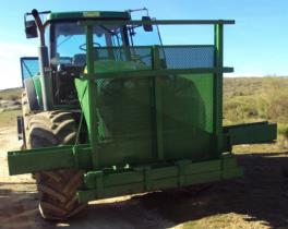

- Model: Biobaler WB55
- Total weight: 6.900 kg
- Base height (A): 0,620 m
- Width (B) 2,5 m
- Height (H): 2,5 m
- Length (L): 5,4 m
- Company: FAE
- Power take-off: Mechanical, doubled to 1.000 rpm from 540 rpm
- Power transmission to rotor: Through belts
- Working width: 2,20 m
- Rotor speed: 1.200 rpm
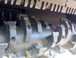
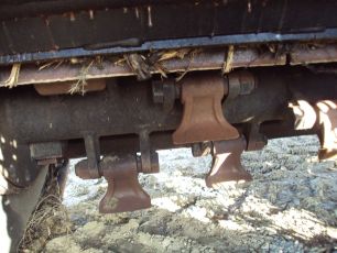
- Cutting tool: 48 hammers/fixed blades (interchangeable)
- Company: ANDERSON
- Transmission to the rollers in the wrapping unit
- Internal diameter of the wrapping deposit: 1,25 m
- Internal length of the wrapping deposit: 1,20 m
- Internal volume of the wrapping deposit: 1.175 m3
- Others: rear viewer
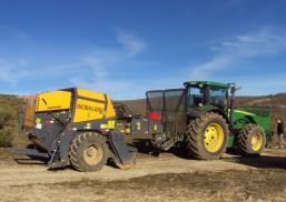
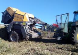
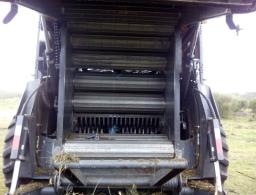
- Dense shrublands with an average height of 1,50 m, or in shrublands under sparse tress.
- Slope less than 15%, that allows mechanization
- Low stoniness and no rocky outcrops that could affect the adequate performance of the harvester systems
- Close to tracks that allow the access of means of transport for the harvested biomass.
